برتر فایل
مجموعه فایل های آموزش مقدماتی تا پیشرفته نرم افزار کتیا (CATIA) و مجموعه کتب, جزوات, پروژه و مقالات تخصصی مهندسی مکانیکبرتر فایل
مجموعه فایل های آموزش مقدماتی تا پیشرفته نرم افزار کتیا (CATIA) و مجموعه کتب, جزوات, پروژه و مقالات تخصصی مهندسی مکانیکآموزش کتیا، مدیریت قطعات الکتریکی در محیط Electrical Library نرم افزار CATIA
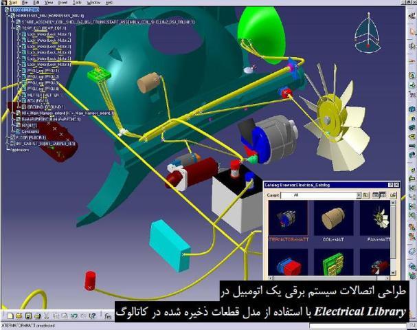
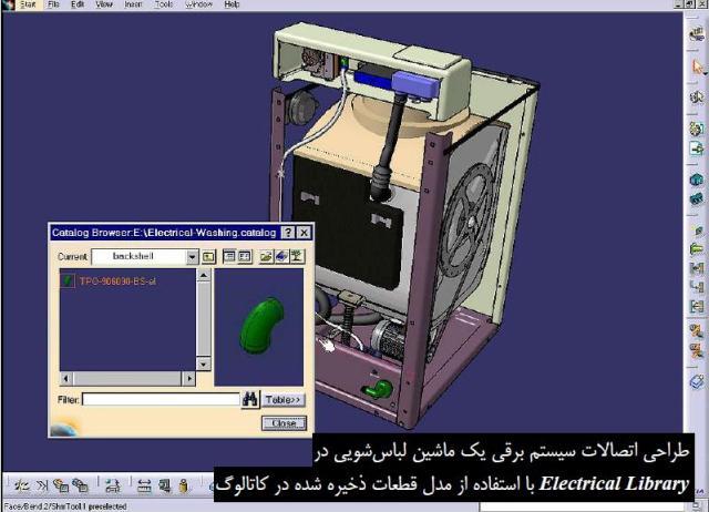
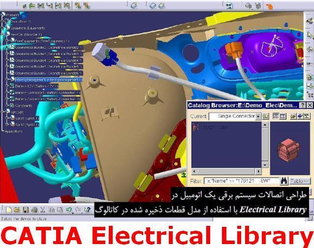
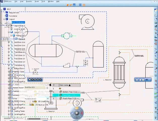
در محیط Electrical Library نرم افزار کتیا، تجهیزات الکتریکی تعریف می شوند. محیط Electrical Library امکان تهیه و مدیریت قطعات الکتریکی، اتصالات و کابل های مورد استفاده را در کاتالوگ های دیجیتالی فراهم آورده است تا همواره قطعات مورد نیاز را برای ایجاد ماکت های دیجیتالی در اختیار داشته باشند. خصوصیات این تجهیزات قابل ویرایش است، مثلا می توان قطر و شکل مقطع، رنگ و مقدار شعاع خم مجاز یک کابل را تغییر داد. سرویس جدیدی که به منظور بهینه سازی فرآیند کار در Electrical Library قرار گرفته است کنترل قطعات و رابطه های بین آن ها در فضای سه بعدی توسط دیاگرام های عملیاتی می باشد.
نقش و کاربرد انواع سنسورها در صنعت و بررسی سنسور پارک خودرو
طراحی و ساخت خودروهای برقی
مدلسازی سیستم کروز کنترل در نرم افزار متلب
این محیط کاری مجموعه ای از دو محیط کاری مستقل Electrical Assembly Design و Electrical Part Design است که به ترتیب برای طراحی در سطح مونتاژ و قطعه اختصاص یافته اند. این دو محیط کاری مشابه محیط Electrical System Functional Definition هستند با این تفاوت که کاملترند...
آموزش مدیریت قطعات الکتریکی در محیط Electrical Library نرم افزار CATIA، یکی از کتاب های مرجع و کاربردی در زمینه آموزش تهیه و مدیریت قطعات الکتریکی، اتصالات و کابل های مورد استفاده در کاتالوگ های دیجیتالی در نرم افزار کتیا می باشد. این کتاب مشتمل بر 350 صفحه، به زبان انگلیسی روان، تایپ شده، به همراه تصاویر رنگی، با فرمت PDF، به ترتیب زیر گردآوری شده است:
Getting Started
Entering the Electrical Part Design Workbench
Defining a Single Insert Connector
Defining a Cavity Connection Point
Entering Electrical Assembly Design Workbench
Accessing Data Through a Catalog
Connecting Electrical Devices
Adding Electrical Behavior to Element Within the Assembly
Inserting New Electrical Part
User Tasks
Using Electrical Library
Entering the Electrical Assembly Design Workbench
Entering the Electrical Part Design Workbench
Defining Electrical Devices
Defining an Equipment
Defining an Electrical Connector
Defining a Filler Plug
Defining a Contact
Defining a Shell
Defining a Back Shell
Defining a Mounting Equipment
Defining Electrical Connection Points
Defining a Cavity
Defining a Termination
Defining a Connector Connection Point
Defining a Bundle Connection Point
Defining a Cavity Connection Point
Defining a Back Shell Connection Point
Creating Supports
Creating Standard Supports
Creating Retainers
Creating an Adaptative Part
Creating Protections
Connecting/Disconnecting Devices
Connecting Electrical Devices
Disconnecting Electrical Devices
Importing Electrical Specifications to Design the 3D Implementation
Working with External Systems
Selective Loading in Electrical Products
Importing Electrical External Data for 3D Implementation
Selecting Systems from External Data
Reconciling External Systems and Physical data
Managing Links from External Data
Removing a Link to a Device
Linking Devices from External Data
Replacing a Device from External Data
Placing Internal Splice by Drag and Drop
Displaying Location Information from External Electrical Specification
Working with Electrical Functional Definition
Placing Physical Devices from Functional Data
Removing Functional Link
Adding Link to Component from Functional Data
Electrical Integration Scenarios
Electrical Integration from External Data
Environment Settings
Setting up the Electrical Process Interfacing
Selecting Systems from External Data
Placing Devices from External Data
Creating the Cable Harness
Placing Internal Splices
Automatic Routing
Exporting Data from CATIA
Electrical Integration from Functional Data
Using Catalogs
Opening Existing Documents Using the Browse Window
Storing a Device
Refining the Catalog Mapping for the Device Storage
Connecting Device by Drag & Drop at Placement
Connecting Contacts by Drag & Drop at Placement
Using Smart Placement from Catalog
Using Smart Move
Working with Wires
Creating Wires Interactively
Creating a Catalog
Creating the Wire References
Describing the CSV File
Editing the Wire Properties
Editing Electrical Properties
Viewing Related Objects
Electrical and Knowledge
Electrical User Functions
Electrical Package in Knowledge Expert
Electrical Application Interoperability
ENOVIA V5 Interoperability
Working with Electrical Data
Optimal CATIA PLM Usability
Using ENOVIA Catalog for Electrical Mapping
Loading an iXF Document with VPM Navigator
Workbench Description
Menu Bar
Toolbars
Electrical Workbench Specification Tree
Customizing
General
Electrical Library Access
Electrical Mapping
Electrical Process Interfacing
Electrical Data Exchange Format
Describing the iXF Electrical Schema
Considering the iXF Schema in Greater Depth
Methodology
Protection of Given Length Methodology
Creating a Protection of Given Length
Instantiating a Protection of Given Length
Using Back Shells as Guiding Supports
Glossary
طراحی دیجیتال و مدار منطقی
سیستم های بیومتریک
آموزش کتیا، مدیریت قطعات الکتریکی در محیط Electrical Library نرم افزار
CATIA
اگر به فراگیری مباحث مشابه مطلب بالا علاقهمند هستید، آموزشهایی که در ادامه آمدهاند نیز به شما پیشنهاد میشوند:
فاصله سنج اولتراسونیک با قابلیت اندازه گیری دما
مدلسازی و شبیه سازی موتور هیسترزیس با نرم افزار متلب
تولید برق بوسیله انرژی جزر و مدی
اجزاء و عملکرد نیروگاه هسته ای
کاربرد متلب در سیگنال ها، سیستم ها و کنترل
طراحی فرکانس متر دیجیتال
دور کننده الکترونیکی حشرات و جانوران
شبیه سازی متعادل سازی بار در شبکه های برق با نرم افزار متلب
کتاب آموزش و تمرین کتیا 2015 جلد دوم (CATIA V5-6R2015 Basics - Part II - Part Modeling Tutorial Books)
کتاب آموزش و تمرین کتیا 2015 (CATIA V5-6R2015 Basics - Part II - Tutorial Books)، یکی از کتاب های مرجع و کاربردی در زمینه آموزش محیط Part Modeling نرم افزار کتیا 2015 می باشد. این کتاب مشتمل بر 180 صفحه، به زبان انگلیسی روان، تایپ شده، به همراه تصاویر رنگی، با فرمت PDF، به ترتیب زیر گردآوری شده است:
Contents
Chapter 3: Basic Sketch Based Features
Pad
Shaft
Project 3D Elements
The Plane command
Offset from plane
Parallel through Point
Through three points
Through two lines
Through point and line
Through planar curve
Normal to curve
Tangent to surface
Equation
Mean through points
Coordinates
On curve
On Plane
On Surface
Circle/Sphere/Ellipse center
Tangent on curve
Between
Line
Additional options of the Pad and Pocket commands
Limits
Thick
View commands
Measure Commands
Examples
Example 1
Example 2
Questions
Exercises
Exercise 1
Exercise 2
Exercise 3
Chapter 4: Holes and Dress-Up Features
Hole
Simple Hole
Counter bored Hole
Countersunk Hole
Tapered Hole
Threaded Hole
The Thread/Tap command
The Edge Fillet command
Limiting elements
Blend corner
Variable Radius Fillet
Chordal Fillet
Face-Face Fillet
Tritangent Fillet
The Chamfer command
Draft Angle
Draft Reflect Line
Variable Angle Draft
Shell
Examples
Example 1
Questions
Exercises
Exercise 1
Exercise 2
Chapter 5: Patterned Geometry
The Mirror command
Rectangular Pattern
Circular Pattern
User Pattern
Scaling
Affinity
Examples
Example 1
Questions
Exercises
Exercise 1
Exercise 2
Chapter 6: Rib Features
The Rib command
The Slot command
Example 1
Questions
Exercise1
Chapter 7: Multi Section Solids
The Multi-sections Solid command
Types of the Cross-sections
Couplings
Spines
Guides
Relimitation
Removed Multi-sections Solid
Example 1
Questions
Exercise 1
Chapter 8: Additional Features and Multi body Parts
Stiffener
Solid Combine
Multi-body Parts
Creating Multi-bodies
Insert in new body
Assemble
Add
Remove
Intersect
Union Trim
Remove Lump
Examples
Example 1 - Millimetres
Questions
Exercises
Exercise 1
Exercise 2
Exercise 3 - Inches
Chapter 9: Modifying Parts
Edit Sketches
Edit Feature Definition
Edit Feature Parameters
Deactivate Features
Activate Features
Changing the Sketch Support
Examples
Example 1
Questions
Exercises
Exercise 1
آموزش بی نظیر نرم افزار کتیا-پارت1
آموزش بی نظیر نرم افزار کتیا-پارت3
کتاب آموزش و تمرین کتیا 2015 جلد دوم (CATIA V5-6R2015 Basics - Part II - Part Modeling Tutorial Books)
اگر به فراگیری مباحث مشابه مطلب بالا علاقهمند هستید، آموزشهایی که در ادامه آمدهاند نیز به شما پیشنهاد میشوند:
از کتیا بیشتر بدانیم
نقشه کشی و نقشه خوانی مهندسی در نرم افزار کتیا
مدلسازی، مونتاژ و نقشه کشی در نرم افزار کتیا
طراحی، مدلسازی، سطح سازی، آنالیز و تحلیل در نرم افزار کتیا
طراحی و مدلسازی، آنالیز و ماشینکاری خودرو مسابقه ای در نرم افزار کتیا
آموزش بی نظیر نرم افزار کتیا
کتاب آموزش جامع ماشینکاری کتیا (CATIA Surface Machining Tutorial Book)
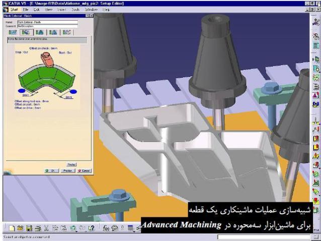
کتاب آموزش جامع ماشینکاری کتیا (CATIA Surface Machining Tutorial Book)، یکی از کتاب های مرجع و کاربردی در زمینه آموزش محیط فرزکاری (Prismatic Machining) نرم افزار کتیا می باشد. این کتاب مشتمل بر 460 صفحه، به زبان انگلیسی روان، تایپ شده، به همراه تصاویر رنگی، با فرمت PDF، به ترتیب زیر گردآوری شده است:
ماشین کاری منشوری در نرم افزار کتیا
اندازه گیری روی ماشین ابزارهای CNC با نرم افزار کتیا
طراحی پروسه ماشینکاری و استخراج G کدهای دستگاه تراش و فرز در نرم افزار CATIA
Preface
Methodology
Getting Started
Operation-oriented Machining
Entering the Workbench
Rough Machining the Part
Z Level Machining of the Outside of a Part
Z Level Machining of the Inside Walls of a Part
Sweeping
Checking the Result of the Operations
Creating an Area to Rework
Reworking
Generating an NC Output File
Generating NC Shop floor Documentation
Area-oriented Machining
Entering the Workbench
Defining the Areas to Machine
Defining the Tools to Use
Rough Machining the Part
Sweeping the Top Surface
Sweeping the Sides
Z Level on the Vertical Walls
Reworking Between Contours
Generating an Output File
Generating Workshop Documentation
Basic Tasks
Rough Machining Operations
Sweep Roughing
Sweep Roughing - Geometric Components
Sweep Roughing - Machining Strategy
Edit the Tool of a Machining Operation
Sweep Roughing - Macro Data
Roughing
Roughing - Geometric Components
Roughing - Machining Strategy
Roughing - Macro Data
Automatic Rough Stock
Finishing and Semi-finishing Operations
Sweeping
Sweeping - Geometric Components
Sweeping - Machining Strategy
Sweeping - Macro Data
Z Level Machining
Z Level Machining - Geometric Components
Z Level - Machining Strategy
Z Level Machining - Macro Data
Spiral Milling
Spiral Milling - Geometric Components
Spiral Milling - Machining Strategy
Spiral Milling - Macro Data
Contour-driven Machining
Contour-driven Machining - Geometric Components
Contour-driven Machining - Machining Strategy
Contour-driven Machining - Macro Data
Create a Profile Contouring Operation
Create a Profile Contouring Operation Between Two Planes
Reworking Operations
Pencil Operations
Pencil - Geometric Components
Pencil - Machining Strategy
Pencil - Macro Data
Roughing Rework Operations
Axial Machining Operations
Create a Spot Drilling Operation
Create a Drilling Operation
Create a Drilling Dwell Delay Operation
Create a Drilling Deep Hole Operation
Create a Drilling Break Chips Operation
Create a Reaming Operation
Create a Counter boring Operation
Create a Boring Operation
Create a Boring Spindle Stop Operation
Create a Boring and Chamfering Operation
Create a Back Boring Operation
Create a Tapping Operation
Create a Reverse Threading Operation
Create a Thread without Tap Head Operation
Create a Thread Milling Operation
Create a Countersinking Operation
Create a Chamfering Two Sides Operation
Create a T-Slotting Operation
Create a Circular Milling Operation
Machining Features
Defining an Area to Machine
Defining an Area to Rework
Defining offsets
Tool Path Editor
Editing a Point on a Tool Path
Editing an Area on a Tool Path
Transformations
Connecting a Tool Path
Reversing a Tool Path
Approaches and Retracts in tool paths
Packing and unpacking a tool path
Checking for Tool Holder Collisions
Reading STL files
Auxiliary Operations
Insert a Tool Change
Edit a Tool Assembly in the Resource List
Insert a Machine Rotation
Insert a Machining Axis or Origin
Insert a PP Instruction
Insert a Copy Transformation Instruction
Part Operations, Programs and Processes
Part Operation
Set Up and Part Positioning
Manufacturing Program
Create a Machining Process
Organize Machining Processes
Apply a Machining Process
Managing Manufacturing Entities
Edit a Tool in the Resource List
Specify Tool Compensation
Machining Patterns
Features
Define Macros on a Milling Operation
Define Macros on an Axial Machining Operation
Status Management
Verification, Simulation and Program Output
Replay a Tool Path
Accessibility on VNC Machine
Machine Management Toolbar
Material Removal Simulation
Material Simulation Settings
Generate APT Source File in Batch Mode
Generate Clfile Code in Batch Mode
Generate NC Code in Batch Mode
Generate a CGR File in Batch Mode
Generate NC Code Interactively
Generate NC Documentation
APT Import
VNC Access
Advanced Tasks
Design Changes
Customizing
NC Manufacturing Settings
Display
Build a Tools Catalog
Tool Resources
Access to External Tool Catalogs
PP Word Syn taxes
PP Tables and PP Word Syntaxes
NC Documentation
Workbench Description
Menu Bar
Toolbars
Manufacturing Program Toolbar
Auxiliary Operations Toolbar
Tool Path Management Toolbar
Machining Features Toolbar
Manufacturing Auxiliary Views Toolbar
Geometry Selection Toolbars
Machining Process Toolbar
NC Manufacturing Toolbars
Workbench Description
Specification Tree
Glossary
Index
طراحی پروسه ماشینکاری 2/5 محوره و استخراج G کدهای دستگاه فرز در CATIA
آموزش ماشین کاری در نرم افزار سرف کم
طراحی پروسه ماشینکاری و استخراج G کدهای دستگاه تراش در نرم افزار کتیا
کتاب آموزش جامع ماشینکاری کتیا (CATIA Surface Machining Tutorial Book)
اگر به فراگیری مباحث مشابه مطلب بالا علاقهمند هستید، آموزشهایی که در ادامه آمدهاند نیز به شما پیشنهاد میشوند:
فاصله سنج اولتراسونیک با قابلیت اندازه گیری دما
مدلسازی و شبیه سازی موتور هیسترزیس با نرم افزار متلب
تولید برق بوسیله انرژی جزر و مدی
اجزاء و عملکرد نیروگاه هسته ای
کاربرد متلب در سیگنال ها، سیستم ها و کنترل
طراحی فرکانس متر دیجیتال
دور کننده الکترونیکی حشرات و جانوران
شبیه سازی متعادل سازی بار در شبکه های برق با نرم افزار متلب
آموزش کتیا، طراحی مدارهای سیستم های توزیع برق و فرمان در محیط Electrical Connectivity Diagrams نرم افزار CATIA
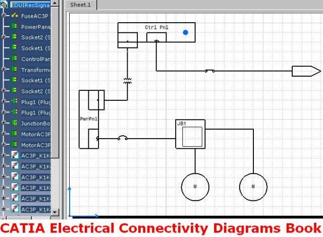
در محیط Electrical Connectivity Diagrams نرم افزار کتیا، مدارهای سیستم های توزیع برق و فرمان با استفاده از علائم استاندارد این سیستم ها طراحی و مدیریت می شود. در واقع از محیط Electrical Connectivity Diagrams برای رسم نقشه های دوبعدی این نوع مدارها استفاده می شود، به همین دلیل قبل از ورود به این محیط کاری باید فضای کاغذ را تعریف کرد (مشابه محیط نقشه کشی صنعتی کتیا یا همان محیط Drafting).
از امکانات محیط Electrical Connectivity Diagrams نرم افزار کتیا می توان به طراحی دوبعدی این نوع سیستم ها در فضای کارخانه یا یک کشتی، طراحی مدارهای نیروگاه های اتمی، پست های توزیع برق، ماشین های ویژه و طراحی مدارهای فرمان خطوط تولید خودکار استفاده کرد. انواع علائم استاندارد نشانگر ژنراتورها، الکترو موتورها، دستگاه های UPS، ترانسفورماتورها، خازن ها، راکتورها، انواع تابلو های کنترل، تابلوهای سوئیچینگ، انباره های جریان مستقیم، یکسوکننده ها، سویچ ها، ترمینال ها، فیوزها و انواع کابل های استاندارد از پیش در محیط Electrical Connectivity Diagrams آماده شده است. توانایی برقراری ارتباط بین نقشه دوبعدی و مدل سه بعدی از دیگر توانایی های محیط Electrical Connectivity Diagrams است. با انجام بررسی بر روی هر کدام از قسمت های نقشه دوبعدی می توان مشخص کرد که نماد هر قسمت با کدام یک از قسمت های دیگر ارتباط دارد...
نقش و کاربرد انواع سنسورها در صنعت و بررسی سنسور پارک خودرو
طراحی و ساخت خودروهای برقی
مدلسازی سیستم کروز کنترل در نرم افزار متلب
مونتاژ سیستم تعلیق خودرو در نرم افزار اتودسک اینونتور
شبیه سازی و آنالیز سیستم تعلیق و فرمان خودرو با نرم افزار آدامز
آموزش طراحی مدارهای سیستم های توزیع برق و فرمان در محیط Electrical Connectivity Diagrams نرم افزار CATIA، یکی از کتاب های مرجع و کاربردی در زمینه آموزش محیط طراحی مدارهای سیستم های توزیع برق و فرمان در نرم افزار کتیا می باشد. این کتاب مشتمل بر 223 صفحه، به زبان انگلیسی روان، تایپ شده، به همراه تصاویر رنگی، با فرمت PDF، به ترتیب زیر گردآوری شده است:
Getting Started
Entering the workbench
Placing components
Routing Cables
Creating a zone
Defining a zone boundary
Saving Documents
User Tasks
Setting up the environment
Building graphic
Create a Component with Specified Type
Define Connectors on a Component
Defining Dynamic Connectors
Define Pins on Component
Manage Potential Connection on Terminal Board
Define Component Group
Define Multiple Representations of a Component
Create a Cable
Setting Graphic Properties of a Cable
Store in Catalog
Designing Electrical Diagrams
Place Components
Repositioning components in a network
Rotating a component
Flipping a component in free space
Flipping a Connected Component
Changing the Scale of a Component
Routing a cable
Modifying a Cable Route
Lock or Unlock a Route
Connecting/Disconnecting objects
Connect objects
Disconnect objects
Managing Publications
Link 2D to 3D
Delete/Unbuild a Component
Measure Distance Between Objects
Move Design Elements
Align Objects
Defining Frame Information
Managing zones
Creating a zone
Creating a zone boundary
Modifying a zone boundary
Updating a zone boundary
Querying a zone
Modifying the properties of a zone
Renaming a zone
Deleting a zone
Managing electrical continuity on switch
Swapping graphic
Using a Knowledge Rule
Managing on and off sheet connectors
Place On and Off Sheet Connector
Link and Unlink On and Off Sheet Connectors
Query Connector for Linked Object
Annotating and printing
Printing a sheet
Create an Annotation with an Attribute Link
Editing Annotation on a Placed Component
Editing electrical properties
Edit or Display Properties of an Object
Filter the Properties of an Object
Renaming Objects
Storing objects in a catalog
Search for Objects in a Diagram
Managing Wire Extremities
Viewing Related Objects
Working with Design Checks
Using ENOVIA
Creating a Product
Importing a Product
Saving a Document in ENOVIA
Saving a Work Package
Workbench Description
Menu Bar
Build Create Toolbar
Terminal Board Toolbar
Design Create Toolbar
Design Modify Toolbar
Cable Create Toolbar
On/Off Sheet Connector Toolbar
Zone Management Toolbar
Schematic Device Storage Toolbar
Catalog Browser Toolbar
Customizing
Customizing Settings
Diagrams
Display
Design Criteria
General
Project Resource Management
PRM for ELD
Understanding Project Resource Management
Checking a PRM File for Errors
Creating Custom Reports
Defining the Report Format
Generating a Report
Generating a Report from a Macro
Creating a Toolbar Shortcut for a Macro
Creating Text Templates
Creating a Text Template
Creating a Text Template Catalog
Placing a Text Template
Adding Template to Reference Component
Setting up the Design Check options
Feature Dictionary: Creating Object Classes and Attributes
Working With ENOVIA
Setup for Enovia
Resources That Must be Placed in ENOVIA
Glossary
طراحی دیجیتال و مدار منطقی
سیستم های بیومتریک
آموزش کتیا، طراحی مدارهای سیستم های توزیع برق و فرمان در محیط Electrical Connectivity Diagrams نرم افزار CATIA
اگر به فراگیری مباحث مشابه مطلب بالا علاقهمند هستید، آموزشهایی که در ادامه آمدهاند نیز به شما پیشنهاد میشوند:
فاصله سنج اولتراسونیک با قابلیت اندازه گیری دما
مدلسازی و شبیه سازی موتور هیسترزیس با نرم افزار متلب
تولید برق بوسیله انرژی جزر و مدی
اجزاء و عملکرد نیروگاه هسته ای
کاربرد متلب در سیگنال ها، سیستم ها و کنترل
طراحی فرکانس متر دیجیتال
دور کننده الکترونیکی حشرات و جانوران
شبیه سازی متعادل سازی بار در شبکه های برق با نرم افزار متلب
کتاب آموزش و تمرین کتیا 2015 جلد اول (CATIA V5-6R2015 Basics - Part I - Sketcher Tutorial Books)
کتاب آموزش و تمرین کتیا 2015 (CATIA V5-6R2015 Basics - PartI - Tutorial Books)، یکی از کتاب های مرجع و کاربردی در زمینه آموزش محیط Sketcher نرم افزار کتیا 2015 می باشد. این کتاب مشتمل بر 78 صفحه، به زبان انگلیسی روان، تایپ شده، به همراه تصاویر رنگی، با فرمت PDF، به ترتیب زیر گردآوری شده است:
Contents
Introduction
Topics covered in this Book
Getting Started with CATIA V5-6R2015
Introduction to CATIA V5-6R2015
File Types in CATIA V5
Starting CATIA V5-6R2015
User Interface
Standard Toolbars
Start Menu
Menu bar
Toolbar
Status bar
Specification Tree
Dialogs
Background
Shortcut Keys
Questions
Sketcher Workbench
Sketching in the Sketcher Workbench
Draw Commands
The Profile command
Polygon
Elongated Hole
Cylindrical Elongated Hole
Keyhole Profile
Line
Infinite Line
Bi-Tangent Line
Bisecting Line
Line Normal to Curve
Axis
Ellipse
Points by Clicking
Point by Using Coordinates
Equidistant Points
Intersection Point
Projection Point
Align Points
Spline
Connect
The Constraint command
Over-constrained Sketch
Auto Constraint
Edit Multi-Constraint
Contact Constraint
Constraints Defined in Dialog
The Fix Together command
Display Geometrical Constraints
Sketch Solving Status
Sketch Analysis
Construction/Standard Element
The Corner command
The Chamfer command
The Quick Trim command
The Break command
The Close Arc command
The Complement command
The Trim command
The Mirror command
The Symmetry command
The Translate command
The Rotate command
The Scale command
The Offset Curve command
Examples
Example 1
Example 2
Questions
Exercises
Exercise 1
Exercise 2
Exercise 3
آموزش بی نظیر نرم افزار کتیا-پارت2
آموزش بی نظیر نرم افزار کتیا-پارت3

کتاب آموزش و تمرین کتیا 2015 جلد اول (CATIA V5-6R2015 Basics - Part I - Sketcher Tutorial Books)
اگر به فراگیری مباحث مشابه مطلب بالا علاقهمند هستید، آموزشهایی که در ادامه آمدهاند نیز به شما پیشنهاد میشوند:
از کتیا بیشتر بدانیم
نقشه کشی و نقشه خوانی مهندسی در نرم افزار کتیا
مدلسازی، مونتاژ و نقشه کشی در نرم افزار کتیا
طراحی، مدلسازی، سطح سازی، آنالیز و تحلیل در نرم افزار کتیا
طراحی و مدلسازی، آنالیز و ماشینکاری خودرو مسابقه ای در نرم افزار کتیا
آموزش بی نظیر نرم افزار کتیا