برتر فایل
مجموعه فایل های آموزش مقدماتی تا پیشرفته نرم افزار کتیا (CATIA) و مجموعه کتب, جزوات, پروژه و مقالات تخصصی مهندسی مکانیکبرتر فایل
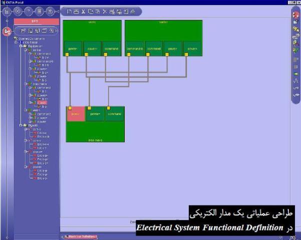
مجموعه فایل های آموزش مقدماتی تا پیشرفته نرم افزار کتیا (CATIA) و مجموعه کتب, جزوات, پروژه و مقالات تخصصی مهندسی مکانیکآموزش کتیا، شرح عملیاتی سیستم های الکتریکی در محیط Electrical System Functional Definition نرم افزار CATIA
محیط Electrical System Functional Definition نرم افزار کتیا، جهت ایجاد شرح عملیاتی (Functional Definition) سیستم های الکتریکی به کار می رود و در اولین مرحله از فرآیند مهندسی این نوع سیستم ها قرار می گیرد. شرح عملیاتی به صورت مستقل از طراحی سه بعدی انجام می شود و ساختار یک سیستم الکتریکی را نشان می دهد. در این شرح، اجزاء و ارتباط بین آنها مشخص می شود و با آن می توان عملکرد سیستم را بررسی کرد . این سیستم می تواند مدار یک تایمر یا یک رادار باشد که با استفاده از یک سیگنال ورودی، شکل سیگنال خروجی را نشان می دهد. باید به این نکته اشاره کرد که با قرار گرفتن CATIA در کنار ENOVIA می توان از این امکان استفاده کرد. به بیان ساده تر محیط Electrical System Functional Definition، یکی از محیط های کاری مستقل CATIA V5 نیست و نمی توان آن را در کنار مجموعه محیط های کاری نرم افزار مشاهده کرد مگر اینکه کاربر ENOVIA نیز بود...
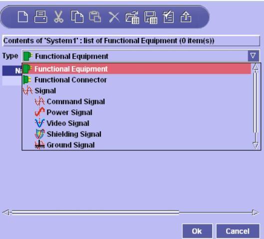
یکی از منوهای Electrical System Functional Definition برای تعریف سیگنال
آموزش شرح عملیاتی سیستم های الکتریکی در محیط Electrical System Functional Definition نرم افزار CATIA، یکی از کتاب های مرجع و کاربردی جهت ایجاد شرح عملیاتی (Functional Definition) سیستم های الکتریکی در نرم افزار کتیا می باشد. این کتاب مشتمل بر 145 صفحه، به زبان انگلیسی روان، تایپ شده، به همراه تصاویر رنگی، با فرمت PDF، به ترتیب زیر گردآوری شده است:
Getting Started
Creating a New System
Creating Equipment
Creating Connectors
Creating a Signal
Connecting
Saving Your System
User Tasks
Installing Electrical System Functional Definition
Starting Electrical System Functional Definition
Creating, Opening & Saving Documents
Creating New Documents
Opening Existing Documents
Closing Documents
Saving Documents
Saving All Documents
Creating Components
Equipment
Connectors
Contact Points
Signals
Copy & Paste
Offsheet Connectors
Working with Catalogs
Store in Catalog
Import from Catalog
Navigating, Editing, Moving, Deleting
Generating a Graphical Preview
Finding Components
Jumping to Connected Objects
Editing Attributes in the Properties View
Editing Attributes in the BOM View
Editing Component Properties
Browsing Signal End Point Attributes
Moving Components Using Cut & Paste
Deleting Components
Electrical Connections
Assigning Signals
Assigning Equipment, Connectors & Contact Points
Connection Flags
Fine-tuning Connections
Making Off Sheet Connections
Analyzing System Connections
Using Data from Other Applications
Printing System Information
Importing & Exporting Systems
About Neutral Files
Importing Systems & Connections
Exporting Systems
Interoperability with Electrical Library
Mapping Functional to Physical
Generating Functional from Physical
Interoperability with ENOVIA V5
Creating New Systems
Opening Existing Systems
Saving Systems in ENOVIA V5
Electrical Integration from Functional Data
Workbench Description
Webtree Toolbar
Document Toolbar
Workshop Commands & Functional Components
Tree View
Customizing
Customizing Electrical System Functional Definition
Setting General Preferences
Setting Units
Glossary
آموزش کتیا، شرح عملیاتی سیستم های الکتریکی در محیط Electrical System Functional Definition نرم افزار CATIA
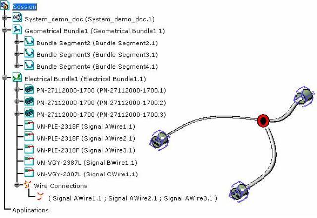
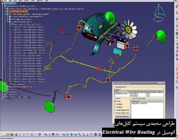
آموزش کتیا، طراحی سیستم کابل ماکت دیجیتالی در محیط Electrical Wire Routing نرم افزار CATIA
در محیط Electrical Wire Routing نرم افزار کتیا، سیستم کابل های یک ماکت دیجیتالی با استفاده از شرح عملیاتی طراحی شده در محیط Electrical System Functional Definition، طراحی و مدل می شود. به نظر می رسد ایجاد و مدیریت سیستم کابل های یک ماکت دیجیتالی به دلیل پیچیدگی آن از مشکل ترین مراحل طراحی یک ماکت دیجیتالی باشد. پس از تکمیل این مراحل، کاربر می تواند تمام ارتباط های الکتریکی بین تجهیزات را شبیه سازی و صحت عملیات کابل کشی را بررسی کند تا از ارتباط مجموعه ها اطمینان حاصل شود. همچنین می توان در یک کلاف شامل تعداد زیادی سیم، سیم مورد نظر و اجزای متصل به آن را یافت. طراح می تواند با استفاده از شرح عملیاتی که برای سیستم الکتریکی در محیط Electrical System Functional Definition ایجاد کرده است سیستم ارتباطات کابلی را ایجاد و مسیر عبور سیگنال را از کابل های مدل شده تعیین نماید.
نقش و کاربرد انواع سنسورها در صنعت و بررسی سنسور پارک خودرو
طراحی و ساخت خودروهای برقی
مدلسازی سیستم کروز کنترل در نرم افزار متلب
آموزش طراحی سیستم کابل ماکت دیجیتالی در محیط Electrical Wire Routing نرم افزار CATIA، یکی از کتاب های مرجع و کاربردی در زمینه آموزش طراحی و مدیریت سیستم کابل های ماکت دیجیتالی در نرم افزار کتیا می باشد. این کتاب مشتمل بر 249 صفحه، به زبان انگلیسی روان، تایپ شده، به همراه تصاویر رنگی، با فرمت PDF، به ترتیب زیر گردآوری شده است:
Getting Started
Accessing the Workbench
Creating the Bundle
Selecting Systems with External Data
Routing Wires from External Data
User Tasks
Starting
Creating the Session
Creating a Bundle
Defining the Working Context for the Routing
Working with External Data
Selecting Systems
Routing Wires
Routing Equipotentials Automatically
Working with Electrical Functional Definition
Selecting the Signal
Creating a Wire
Routing Wires Automatically
Modifying a Wire Route
Deleting a Wire
Working with Signal Routes
Reconciling Objects
Creating a Signal Route
Deleting a Signal Route
Electrical Integration Scenarios
Electrical Integration from External Data
Environment Settings
Setting up the Electrical Process Interfacing
Selecting Systems from External Data
Placing Devices from External Data
Creating the Cable Harness
Placing Internal Splices
Automatic Routing
Exporting Data from CATIA
Electrical Integration from Functional Data
Working with Wire Connections
Creating a Wire Connection
Moving a Wire Connection
Deleting a Wire Connection
Merging Wire Connections
Splitting Wire Connection
Accessing Data From Catalog Using Electrical Library
Getting Wire References
Resolving Internal Splices
Exporting Wires
Managing the Wire Extremities
Simulating the Routing
Managing Pathway/Signal Compatibility with Knowledgeware during Automatic Routing
Filtering Wires Based on External Configuration System
Editing Electrical Properties
Viewing Related Objects
Electrical and Knowledge
Electrical User Functions
Electrical Package in Knowledge Expert
Electrical Application Interoperability
ENOVIA V5 Interoperability
Working with Electrical Data
Optimal CATIA PLM Usability
Using ENOVIA Catalog for Electrical Mapping
Loading an iXF Document with VPM Navigator
Workbench Description
Menu Bar
Toolbars
Specification Tree
Electrical Workbench Specification Tree
Customizing
Electrical Wire Routing
Electrical Mapping
Electrical Process Interfacing
Using Compatibility Table
Cache Management
Electrical Data Exchange Format
Describing the iXF Electrical Schema
Considering the iXF Schema in Greater Depth
Glossary
طراحی دیجیتال و مدار منطقی
سیستم های بیومتریک
آموزش کتیا، طراحی سیستم کابل ماکت دیجیتالی در محیط Electrical Wire Routing نرم افزار CATIA
اگر به فراگیری مباحث مشابه مطلب بالا علاقهمند هستید، آموزشهایی که در ادامه آمدهاند نیز به شما پیشنهاد میشوند:
فاصله سنج اولتراسونیک با قابلیت اندازه گیری دما
مدلسازی و شبیه سازی موتور هیسترزیس با نرم افزار متلب
تولید برق بوسیله انرژی جزر و مدی
اجزاء و عملکرد نیروگاه هسته ای
کاربرد متلب در سیگنال ها، سیستم ها و کنترل
طراحی فرکانس متر دیجیتال
دور کننده الکترونیکی حشرات و جانوران
شبیه سازی متعادل سازی بار در شبکه های برق با نرم افزار متلب
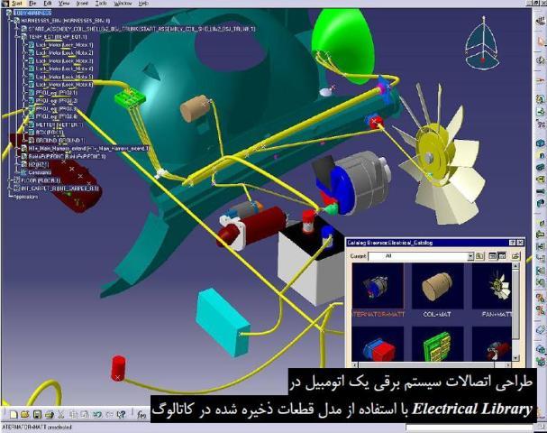
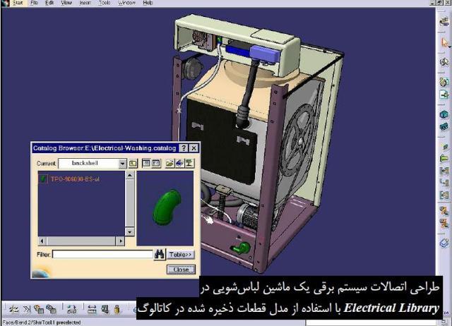
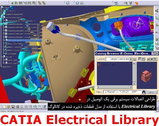
آموزش کتیا، مدیریت قطعات الکتریکی در محیط Electrical Library نرم افزار CATIA
در محیط Electrical Library نرم افزار کتیا، تجهیزات الکتریکی تعریف می شوند. محیط Electrical Library امکان تهیه و مدیریت قطعات الکتریکی، اتصالات و کابل های مورد استفاده را در کاتالوگ های دیجیتالی فراهم آورده است تا همواره قطعات مورد نیاز را برای ایجاد ماکت های دیجیتالی در اختیار داشته باشند. خصوصیات این تجهیزات قابل ویرایش است، مثلا می توان قطر و شکل مقطع، رنگ و مقدار شعاع خم مجاز یک کابل را تغییر داد. سرویس جدیدی که به منظور بهینه سازی فرآیند کار در Electrical Library قرار گرفته است کنترل قطعات و رابطه های بین آن ها در فضای سه بعدی توسط دیاگرام های عملیاتی می باشد.
نقش و کاربرد انواع سنسورها در صنعت و بررسی سنسور پارک خودرو
طراحی و ساخت خودروهای برقی
مدلسازی سیستم کروز کنترل در نرم افزار متلب
این محیط کاری مجموعه ای از دو محیط کاری مستقل Electrical Assembly Design و Electrical Part Design است که به ترتیب برای طراحی در سطح مونتاژ و قطعه اختصاص یافته اند. این دو محیط کاری مشابه محیط Electrical System Functional Definition هستند با این تفاوت که کاملترند...
آموزش مدیریت قطعات الکتریکی در محیط Electrical Library نرم افزار CATIA، یکی از کتاب های مرجع و کاربردی در زمینه آموزش تهیه و مدیریت قطعات الکتریکی، اتصالات و کابل های مورد استفاده در کاتالوگ های دیجیتالی در نرم افزار کتیا می باشد. این کتاب مشتمل بر 350 صفحه، به زبان انگلیسی روان، تایپ شده، به همراه تصاویر رنگی، با فرمت PDF، به ترتیب زیر گردآوری شده است:
Getting Started
Entering the Electrical Part Design Workbench
Defining a Single Insert Connector
Defining a Cavity Connection Point
Entering Electrical Assembly Design Workbench
Accessing Data Through a Catalog
Connecting Electrical Devices
Adding Electrical Behavior to Element Within the Assembly
Inserting New Electrical Part
User Tasks
Using Electrical Library
Entering the Electrical Assembly Design Workbench
Entering the Electrical Part Design Workbench
Defining Electrical Devices
Defining an Equipment
Defining an Electrical Connector
Defining a Filler Plug
Defining a Contact
Defining a Shell
Defining a Back Shell
Defining a Mounting Equipment
Defining Electrical Connection Points
Defining a Cavity
Defining a Termination
Defining a Connector Connection Point
Defining a Bundle Connection Point
Defining a Cavity Connection Point
Defining a Back Shell Connection Point
Creating Supports
Creating Standard Supports
Creating Retainers
Creating an Adaptative Part
Creating Protections
Connecting/Disconnecting Devices
Connecting Electrical Devices
Disconnecting Electrical Devices
Importing Electrical Specifications to Design the 3D Implementation
Working with External Systems
Selective Loading in Electrical Products
Importing Electrical External Data for 3D Implementation
Selecting Systems from External Data
Reconciling External Systems and Physical data
Managing Links from External Data
Removing a Link to a Device
Linking Devices from External Data
Replacing a Device from External Data
Placing Internal Splice by Drag and Drop
Displaying Location Information from External Electrical Specification
Working with Electrical Functional Definition
Placing Physical Devices from Functional Data
Removing Functional Link
Adding Link to Component from Functional Data
Electrical Integration Scenarios
Electrical Integration from External Data
Environment Settings
Setting up the Electrical Process Interfacing
Selecting Systems from External Data
Placing Devices from External Data
Creating the Cable Harness
Placing Internal Splices
Automatic Routing
Exporting Data from CATIA
Electrical Integration from Functional Data
Using Catalogs
Opening Existing Documents Using the Browse Window
Storing a Device
Refining the Catalog Mapping for the Device Storage
Connecting Device by Drag & Drop at Placement
Connecting Contacts by Drag & Drop at Placement
Using Smart Placement from Catalog
Using Smart Move
Working with Wires
Creating Wires Interactively
Creating a Catalog
Creating the Wire References
Describing the CSV File
Editing the Wire Properties
Editing Electrical Properties
Viewing Related Objects
Electrical and Knowledge
Electrical User Functions
Electrical Package in Knowledge Expert
Electrical Application Interoperability
ENOVIA V5 Interoperability
Working with Electrical Data
Optimal CATIA PLM Usability
Using ENOVIA Catalog for Electrical Mapping
Loading an iXF Document with VPM Navigator
Workbench Description
Menu Bar
Toolbars
Electrical Workbench Specification Tree
Customizing
General
Electrical Library Access
Electrical Mapping
Electrical Process Interfacing
Electrical Data Exchange Format
Describing the iXF Electrical Schema
Considering the iXF Schema in Greater Depth
Methodology
Protection of Given Length Methodology
Creating a Protection of Given Length
Instantiating a Protection of Given Length
Using Back Shells as Guiding Supports
Glossary
طراحی دیجیتال و مدار منطقی
سیستم های بیومتریک
آموزش کتیا، مدیریت قطعات الکتریکی در محیط Electrical Library نرم افزار
CATIA
اگر به فراگیری مباحث مشابه مطلب بالا علاقهمند هستید، آموزشهایی که در ادامه آمدهاند نیز به شما پیشنهاد میشوند:
فاصله سنج اولتراسونیک با قابلیت اندازه گیری دما
مدلسازی و شبیه سازی موتور هیسترزیس با نرم افزار متلب
تولید برق بوسیله انرژی جزر و مدی
اجزاء و عملکرد نیروگاه هسته ای
کاربرد متلب در سیگنال ها، سیستم ها و کنترل
طراحی فرکانس متر دیجیتال
دور کننده الکترونیکی حشرات و جانوران
شبیه سازی متعادل سازی بار در شبکه های برق با نرم افزار متلب
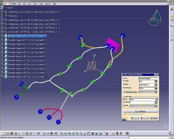
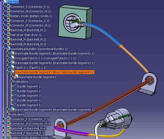
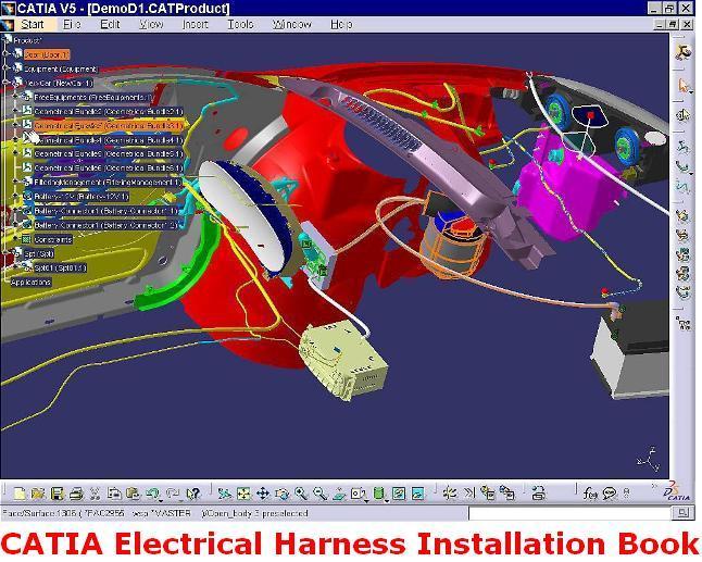
آموزش کتیا، طراحی سیستم کابل مجموعه مونتاژی بر روی مدل دیجیتالی در محیط Electrical Harness Assembly نرم افزار CATIA
در محیط Electrical Harness Installation نرم افزار کتیا، سیستم کابل یک مجموعه مونتاژی بر روی مدل دیجیتالی آن پیاده سازی می شود. این محیط کاری مخصوص مونتاژ کابل های سیستم های الکتریکی در کنار سایر قطعات یک مجموعه می باشد. مسیر عبور دسته ای از کابل ها با روش هایی همچون عبور کابل از نقاط مشخص، تبعیت مسیر عبور کابل از فرم خارجی بدنه، عبور کابل از نگه دارنده های مخصوص سیستم های الکتریکی، تبعیت مسیر عبور کابل از یک منحنی یا مارپیچی مشخص می شود. تمام خصوصیات یک کابل مانند لَختی در هنگام عبور از تکیه گاه ها که باعث ایجاد انحنا در کابل می شود یا قطر کلافی از کابل ها که مانع خم شدن بیش از یک شعاع مشخص است شبیه سازی می شود. این ابزارها از توانایی های Flex Physical Simulation می باشد که به Equipment & Systems Engineering افزوده می شود. پس از تکمیل این مراحل، کاربر می تواند تمام ارتباطات بین تجهیزات را شبیه سازی کند و صحت عملیات را کنترل نماید. برای استفاده از امکانات این محیط کاری باید گزینه Electrical Harness Assembly را از منوی Start نرم افزار CATIA انتخاب کرد.
نقش و کاربرد انواع سنسورها در صنعت و بررسی سنسور پارک خودرو
طراحی و ساخت خودروهای برقی
مدلسازی سیستم کروز کنترل در نرم افزار متلب
با استفاده از امکانات Flex Physical Simulation خصوصیات واقعی در سیستم کابلی یک محصول اعمال می شود. از این خصوصیات می توان به در نظر گرفتن وزن، انعطاف پذیری و رفتار غیر خطی سیم اشاره کرد. امکانات Flex Physical Simulation به EHI (در مجموعه Equipment & Systems Engineering) که مختص طراحی سیستم کابلی یک مجموعه مونتاژی است افزوده می شود...
طراحی دیجیتال و مدار منطقی
سیستم های بیومتریک
آموزش طراحی سیستم کابل مجموعه مونتاژی بر روی مدل دیجیتالی در محیط Electrical Harness Assembly نرم افزار CATIA، یکی از کتاب های مرجع و کاربردی در زمینه آموزش محیط طراحی سیستم کابل یک مجموعه مونتاژی بر روی مدل دیجیتالی و پیاده سازی آن در نرم افزار کتیا می باشد. این کتاب مشتمل بر 413 صفحه، به زبان انگلیسی روان، تایپ شده، به همراه تصاویر رنگی، با فرمت PDF، به ترتیب زیر گردآوری شده است:
Getting Started
Entering the Workbench
Setting Up the Options
Creating a Bundle Segment Document
Creating Construction Points
Defining the Segment Parameters
Defining the Segment Route
Adding a Branch Point
User Tasks
Entering the Workbench
Creating a Geometrical Bundle
Selective Loading in Electrical Products
Creating a Bundle Segment Document
Creating Construction Constraints
Creating Lines
Creating Planes
Creating Points
Defining the Segment Parameters
Defining the Segment Route
Routing Bundle Segments from Construction Points
Routing Bundle Segments through Retainers
Routing Bundle Segments Following a Part using the Manipulator
Routing Bundle Segments Following a Part
Routing Bundle Segments from an Existing Helix
Detailing the Routing Options
Sharp Bending Bundle Segment
Exiting the Installation Workbench
Working with Branches
Creating all the Bundle Segments in a Single Part
Creating Other Segments within a Branch
Removing a Branch Point
Branching External Bundle Segments
Using Delete Special... on Branches
Using Branchable Bundle Segments in V5R12 Onwards
Creating/Using Branch Points
Adding Branch Points
Removing Branch Points
Routing Bundle Segments in Support
Adding Support
Removing Support
Linking/Unlinking Bundle Segments
Linking Bundle Segments
Unlinking Bundle Segments
Splitting Bundle Segments
Splitting Branchable Bundle Segments
Splitting Single Bundle Segments
Transferring Branches
Split and Transfer Usage
Instantiating a Protection
Adding Local Slack
Working with 3D Tolerancing
Using the Mechanical Modeler Integration
Measuring Geometrical Bundle Inertia
Inertia Equivalents
V4/V5 Electrical Data Migration
Methodology
Migrating Step by Step
V4 - V5 Mapping
Reference Information
Frequently Asked Questions
Electrical Integration Scenarios
Electrical Integration from External Data
Environment Settings
Setting up the Electrical Process Interfacing
Selecting Systems from External Data
Placing Devices from External Data
Creating the Cable Harness
Placing Internal Splices
Automatic Routing
Exporting Data from CATIA
Electrical Integration from Functional Data
Editing Electrical Properties
Viewing Related Objects
Electrical and Knowledge
Electrical User Functions
Electrical Package in Knowledge Expert
Electrical Application Interoperability
ENOVIA V5 Interoperability
Working with Electrical Data
Optimal CATIA PLM Usability
Using ENOVIA Catalog for Electrical Mapping
Loading an iXF Document with VPM Navigator
Workbench Description
Menu Bar
Toolbars
Electrical Workbench Specification Tree
Customizing
Electrical Harness Installation
Part Infrastructure
Compatibility
Product Structure
Methodology
Protection of Given Length Methodology
Creating a Protection of Given Length
Instantiating a Protection of Given Length
Flat Cable Methodology
Defining a Specific Support for Flat Cable
Creating the Line and Placing the Supports
Creating the Flat Cable
Creating the Bundle Segments
Creating the Square Shape
Extracting and Flattening the Cable
Creating an Adaptative Part
Glossary
سیستم تعلیق خودرو برای یک چرخ
معرفی و بررسی انواع سیستم های ترمز خودرو
روش طراحی انواع کمک فنرها
بررسی و آشنایی با انواع فنربندی و سیستم تعلیق خودرو
جهت دانلود آموزش طراحی سیستم کابل مجموعه مونتاژی بر روی مدل دیجیتالی در محیط Electrical Harness Assembly نرم افزار CATIA برلینک زیر کلیک نمایید:
آموزش کتیا، طراحی سیستم کابل مجموعه مونتاژی بر روی مدل دیجیتالی در محیط Electrical Harness Assembly نرم افزار CATIA
اگر به فراگیری مباحث مشابه مطلب بالا علاقهمند هستید، آموزشهایی که در ادامه آمدهاند نیز به شما پیشنهاد میشوند:
فاصله سنج اولتراسونیک با قابلیت اندازه گیری دما
مدلسازی و شبیه سازی موتور هیسترزیس با نرم افزار متلب
تولید برق بوسیله انرژی جزر و مدی
اجزاء و عملکرد نیروگاه هسته ای
کاربرد متلب در سیگنال ها، سیستم ها و کنترل
طراحی فرکانس متر دیجیتال
دور کننده الکترونیکی حشرات و جانوران
شبیه سازی متعادل سازی بار در شبکه های برق با نرم افزار متلب
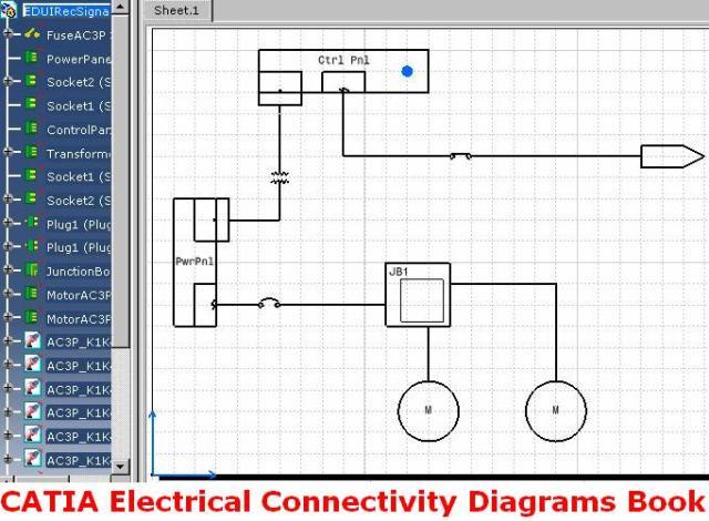
آموزش کتیا، طراحی مدارهای سیستم های توزیع برق و فرمان در محیط Electrical Connectivity Diagrams نرم افزار CATIA
در محیط Electrical Connectivity Diagrams نرم افزار کتیا، مدارهای سیستم های توزیع برق و فرمان با استفاده از علائم استاندارد این سیستم ها طراحی و مدیریت می شود. در واقع از محیط Electrical Connectivity Diagrams برای رسم نقشه های دوبعدی این نوع مدارها استفاده می شود، به همین دلیل قبل از ورود به این محیط کاری باید فضای کاغذ را تعریف کرد (مشابه محیط نقشه کشی صنعتی کتیا یا همان محیط Drafting).
از امکانات محیط Electrical Connectivity Diagrams نرم افزار کتیا می توان به طراحی دوبعدی این نوع سیستم ها در فضای کارخانه یا یک کشتی، طراحی مدارهای نیروگاه های اتمی، پست های توزیع برق، ماشین های ویژه و طراحی مدارهای فرمان خطوط تولید خودکار استفاده کرد. انواع علائم استاندارد نشانگر ژنراتورها، الکترو موتورها، دستگاه های UPS، ترانسفورماتورها، خازن ها، راکتورها، انواع تابلو های کنترل، تابلوهای سوئیچینگ، انباره های جریان مستقیم، یکسوکننده ها، سویچ ها، ترمینال ها، فیوزها و انواع کابل های استاندارد از پیش در محیط Electrical Connectivity Diagrams آماده شده است. توانایی برقراری ارتباط بین نقشه دوبعدی و مدل سه بعدی از دیگر توانایی های محیط Electrical Connectivity Diagrams است. با انجام بررسی بر روی هر کدام از قسمت های نقشه دوبعدی می توان مشخص کرد که نماد هر قسمت با کدام یک از قسمت های دیگر ارتباط دارد...
نقش و کاربرد انواع سنسورها در صنعت و بررسی سنسور پارک خودرو
طراحی و ساخت خودروهای برقی
مدلسازی سیستم کروز کنترل در نرم افزار متلب
مونتاژ سیستم تعلیق خودرو در نرم افزار اتودسک اینونتور
شبیه سازی و آنالیز سیستم تعلیق و فرمان خودرو با نرم افزار آدامز
آموزش طراحی مدارهای سیستم های توزیع برق و فرمان در محیط Electrical Connectivity Diagrams نرم افزار CATIA، یکی از کتاب های مرجع و کاربردی در زمینه آموزش محیط طراحی مدارهای سیستم های توزیع برق و فرمان در نرم افزار کتیا می باشد. این کتاب مشتمل بر 223 صفحه، به زبان انگلیسی روان، تایپ شده، به همراه تصاویر رنگی، با فرمت PDF، به ترتیب زیر گردآوری شده است:
Getting Started
Entering the workbench
Placing components
Routing Cables
Creating a zone
Defining a zone boundary
Saving Documents
User Tasks
Setting up the environment
Building graphic
Create a Component with Specified Type
Define Connectors on a Component
Defining Dynamic Connectors
Define Pins on Component
Manage Potential Connection on Terminal Board
Define Component Group
Define Multiple Representations of a Component
Create a Cable
Setting Graphic Properties of a Cable
Store in Catalog
Designing Electrical Diagrams
Place Components
Repositioning components in a network
Rotating a component
Flipping a component in free space
Flipping a Connected Component
Changing the Scale of a Component
Routing a cable
Modifying a Cable Route
Lock or Unlock a Route
Connecting/Disconnecting objects
Connect objects
Disconnect objects
Managing Publications
Link 2D to 3D
Delete/Unbuild a Component
Measure Distance Between Objects
Move Design Elements
Align Objects
Defining Frame Information
Managing zones
Creating a zone
Creating a zone boundary
Modifying a zone boundary
Updating a zone boundary
Querying a zone
Modifying the properties of a zone
Renaming a zone
Deleting a zone
Managing electrical continuity on switch
Swapping graphic
Using a Knowledge Rule
Managing on and off sheet connectors
Place On and Off Sheet Connector
Link and Unlink On and Off Sheet Connectors
Query Connector for Linked Object
Annotating and printing
Printing a sheet
Create an Annotation with an Attribute Link
Editing Annotation on a Placed Component
Editing electrical properties
Edit or Display Properties of an Object
Filter the Properties of an Object
Renaming Objects
Storing objects in a catalog
Search for Objects in a Diagram
Managing Wire Extremities
Viewing Related Objects
Working with Design Checks
Using ENOVIA
Creating a Product
Importing a Product
Saving a Document in ENOVIA
Saving a Work Package
Workbench Description
Menu Bar
Build Create Toolbar
Terminal Board Toolbar
Design Create Toolbar
Design Modify Toolbar
Cable Create Toolbar
On/Off Sheet Connector Toolbar
Zone Management Toolbar
Schematic Device Storage Toolbar
Catalog Browser Toolbar
Customizing
Customizing Settings
Diagrams
Display
Design Criteria
General
Project Resource Management
PRM for ELD
Understanding Project Resource Management
Checking a PRM File for Errors
Creating Custom Reports
Defining the Report Format
Generating a Report
Generating a Report from a Macro
Creating a Toolbar Shortcut for a Macro
Creating Text Templates
Creating a Text Template
Creating a Text Template Catalog
Placing a Text Template
Adding Template to Reference Component
Setting up the Design Check options
Feature Dictionary: Creating Object Classes and Attributes
Working With ENOVIA
Setup for Enovia
Resources That Must be Placed in ENOVIA
Glossary
طراحی دیجیتال و مدار منطقی
سیستم های بیومتریک
آموزش کتیا، طراحی مدارهای سیستم های توزیع برق و فرمان در محیط Electrical Connectivity Diagrams نرم افزار CATIA
اگر به فراگیری مباحث مشابه مطلب بالا علاقهمند هستید، آموزشهایی که در ادامه آمدهاند نیز به شما پیشنهاد میشوند:
فاصله سنج اولتراسونیک با قابلیت اندازه گیری دما
مدلسازی و شبیه سازی موتور هیسترزیس با نرم افزار متلب
تولید برق بوسیله انرژی جزر و مدی
اجزاء و عملکرد نیروگاه هسته ای
کاربرد متلب در سیگنال ها، سیستم ها و کنترل
طراحی فرکانس متر دیجیتال
دور کننده الکترونیکی حشرات و جانوران
شبیه سازی متعادل سازی بار در شبکه های برق با نرم افزار متلب